Email: Gustavo@hengrytech.com Tel: +86-577-67318236
![]()
![]()
![]()
![]()
![]()
Email: Gustavo@hengrytech.com Tel: +86-577-67318236
![]()
![]()
![]()
![]()
![]()

Technical parameters:
Power supply: standard industrial electricity - AC380V, 50HZ, three-phase five-wire system;
Control voltage: safety control voltage - DC24V;
Use of environmental requirements: moisture-proof, dust-proof environment;
Total power of the system: <=3KW.
System safe use of pressure: P <= 7Mpa.
Dimensions: 2200×980×1150 (mm);.
Weight of the whole machine: about 300Kg.
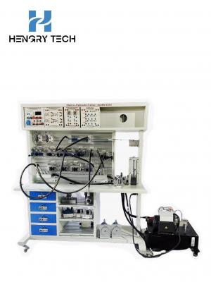
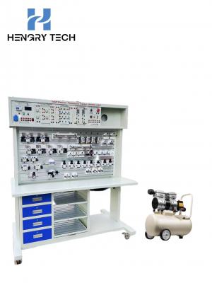
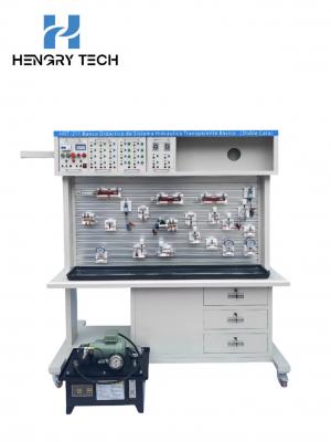
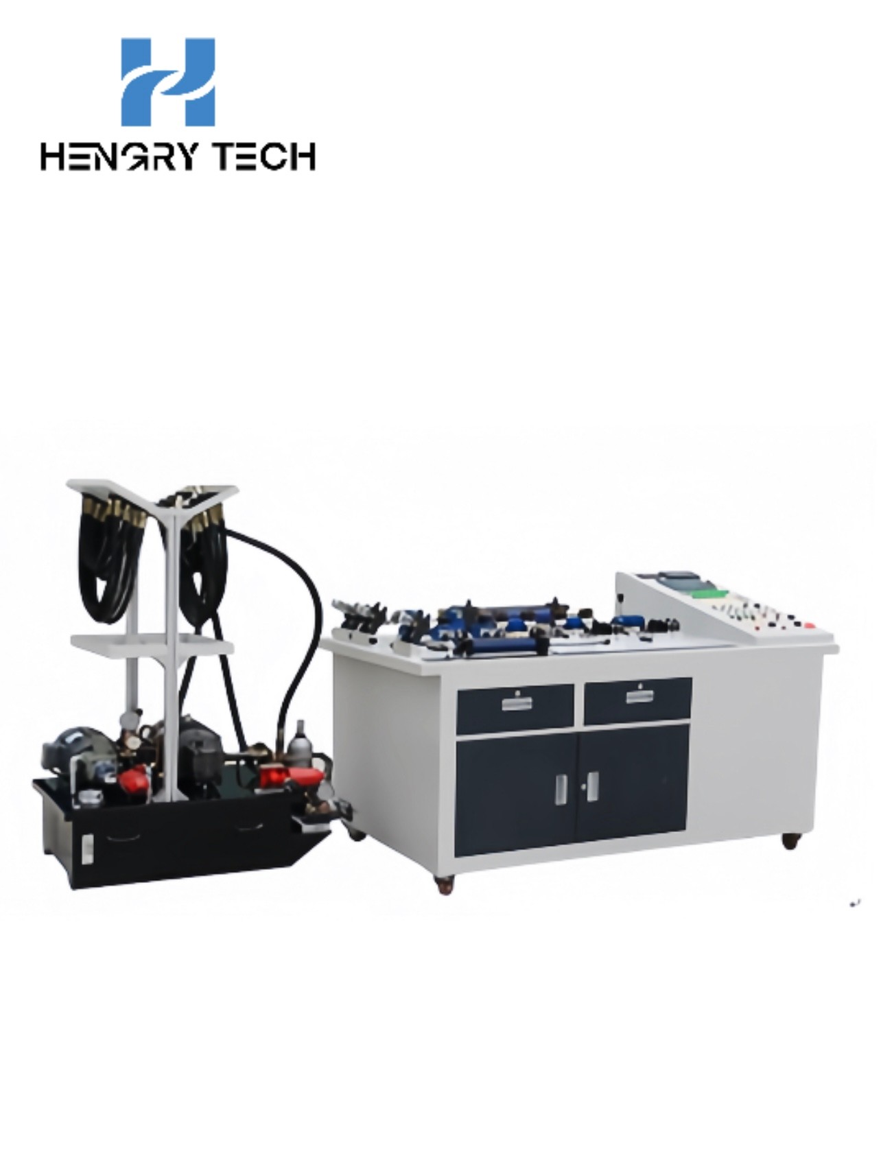
Product Overview
HR-GY02 Intelligent hydraulic transmission trainer consists of practical training platform, electrical control platform, computer table, data acquisition system, upper unit configuration simulation control system, etc. It has powerful data acquisition and experimental simulation functions. Not only can help students to complete the basic hydraulic transmission and fluid mechanics related basic experiments, intelligent data system can help students to complete the design of hydraulic transmission innovation comprehensive experiments. The design function of this experimental bench can not only meet the requirements of basic experiments for college students, but also meet the requirements of teaching and scientific research with the accompanying extended function, which is very suitable for postgraduates, teachers, experts and engineers in the field of hydraulics to engage in teaching and scientific research work.
Main features.
1. The system all adopts standard industrial hydraulic components: the use of safe and reliable, close to industrialization. All hydraulic valves are used in the international advanced technology hydraulic components, performance parameters in full compliance with the requirements of the syllabus, and fully in line with industrial application standards;
2. Experimental circuit plug and play: experimental trainees can quickly understand the function of the experimental bench, quickly master the operating skills, and quickly complete the experimental operation. Connection method adopts quick-change joints, each joint is equipped with a one-way valve with self-locking structure (even if the joints are not connected and fall off in the course of the experiment, there will be no pressure oil sprayed out to ensure the safety of the experiment), the internal sealing material utilizes the latest international sealing material - PTFE sealing ring, replacing the traditional nitrile material, which solves the problem of oil leakage that has not yet been overcome by the majority of other manufacturers. The internal sealing material utilizes the latest international sealing material - PTFE sealing ring instead of the traditional nitrile material, which solves the problem of oil leakage that most other manufacturers have not yet overcome and ensures the cleanliness of the experimental process;
3. Diversified experimental control: the experimental circuit can use mechanical control, traditional relay control, advanced PLC automatic control and other control technologies, so that the students can have an all-round, multi-level in-depth understanding of the control of the hydraulic system diversified, so as to exercise the students' flexible application capabilities;
4. Experimental equipment has a very expandable space: experimental configuration program can be configured according to specific requirements, but also on the experimental equipment to increase components and other control methods to enhance the function of the experimental bench, components are standardized connectors, the late addition of new components are compatible with the experimental bench;
5. Programmable logic controller (PLC) can communicate with the PC: to realize the electrical automation control, online programming monitoring and fault detection, as well as the use of PC and PLC hydraulic control system for in-depth secondary development;
6. mobile modular design of the experimental bench: in the design of the experimental bench is not only a combination of ergonomics, international popular design concepts, product features and other factors, as far as possible, the experimental bench beautiful and lightweight, in line with the aesthetic requirements, but also on the reliability of the experimental bench, safety, service life and so on is also unambiguous, to break the traditional design concepts;
7. Rich configuration simulation software: provides up to 20 simulation/monitoring of commonly used circuits, circuits can be monitored to each of the valve core action, fluid flow, pressure, actuator action, as well as PLC I/O interface input/output situation. All kinds of monitoring conditions are visualized on the monitoring screen in the form of picture color distinction/text, which is very intuitive and clear;
8. Equipped with advanced high-precision measuring instruments: high stability data measuring instruments, instead of traditional measuring tools, easy to use, accurate and reliable measurement;
9. Stable and reliable data acquisition system: using imported 12 precision 8-channel I/O AD data acquisition card, to ensure that the experimental data is accurate, interference is small, and stability is higher than other products of the same type; I/O channels can be expanded according to the needs of self-expansion, easy and convenient to operate, the software adopts the original system with independent intellectual property rights and stable performance, according to the needs of real-time curves, generating reports, generating X-Y curve, data accuracy and system stability, and the system is stable. Y curve, accurate data and stable system;
10. excellent hydraulic oil supply system: hydraulic oil pump using flange mounting, greatly reducing the noise of the work operation, and the hydraulic oil supply system on the basis of the conventional increase in safety valves, etc., to play a secondary role in protection, to ensure the safety of the experiment;
11. High safety level: the design of the experimental bench in full accordance with national safety standards, all electrical controls are grounding protection, overload protection, short circuit protection, leakage protection and other functions, with a high degree of safety performance.
Experimental items.
1. Performance testing of commonly used hydraulic components (hydraulic pumps, relief valves, pressure reducing valves, throttle valves, etc.) Hydraulic drive basic circuit experiments: (more than thirty kinds of circuits)
2. Pressure control circuit:
3. Relief valve pressure regulating circuit;
4. Relief valve single-stage remote pressure regulating circuit;
5. Multi-stage relief valve pressure regulating circuit;
6. relief valve limiting low-pressure circuits;
7. Variable pressure circuits:
8. primary pressure reducing circuits;
9. two-stage pressure-reducing circuits;
10. Multi-stage pressure reducing circuits.
11. Unloading circuit:
12. three-position four-way electromagnetic reversing unloading circuit;
13. Two-position three-way electromagnetic directional valve unloading circuit;
14. Relief valve unloading circuit.
15. Pressure stabilizing circuit:
16. Accumulator pressure stabilizing circuit;
17. Pilot operated check valve pressure maintaining circuit.
18. Pressure relief circuit:
19. Throttle valve unloading circuit;
20. Sequence valve pressure relief circuit.
21. Speed control circuit:
22. Inlet oil throttling speed control circuit
23. Return throttle speed control circuit;
24. Bypass throttle speed control circuit;
25. Speed control circuit controlled by speed control valve;
26.Differential connection speed increasing circuit;
27. Accumulator speed increasing circuit;
28. deceleration circuits for speed regulation with solenoid valves and speed control valves connected in series;
29. secondary feeding circuits with speed control valves connected in series;
30. secondary feeding circuits with speed-regulating valves connected in parallel;
31. secondary feeding circuits with throttle valves connected in series;
32. secondary feeding circuits with throttle valves connected in parallel;
33. differential circuits with two-position three-way control;
34. differential circuits for three-position four-way control;
35. three times feeding circuits;
36. differential working commutation circuits;
37. synchronized circuits:
38. throttle-controlled synchronizing circuits;
39. double-cylinder synchronizing circuits;
40. synchronizing circuits controlled by speed control valves;
41. Direction control circuits:
42. directional control circuits controlled by directional valves;
43. Sequential action circuits controlled by sequence valves;
44. Sequential working circuits controlled by travel switches;
45. pressure relay controlled point sequential action circuits.
46. locking circuits:
47. Directional valve locking circuits;
48. locking circuits for pilot operated check valves;
49. locking circuit of check valve;
50. Balancing circuits:
51. balancing circuits for pilot operated check valves;
52. Balancing circuits for sequence valve control.
Programmable logic controller (PLC) electrical control experiments:
1), PLC instruction programming, ladder programming and other basic knowledge learning application;
2), PLC programming software learning and use;
3), PLC and computer communication, online debugging, monitoring;
4), configuration software and PLC communication and monitoring experimental learning.
Contact: Gustavo Zhang
Phone: +86 18966252578
Tel: +86-577-67318236
Email: Gustavo@hengrytech.com
Add: Yongjia county, wenzhou city, zhejiang province ou the five-star industrial zone north street