Email: Gustavo@hengrytech.com Tel: +86-577-67318236
![]()
![]()
![]()
![]()
![]()
Email: Gustavo@hengrytech.com Tel: +86-577-67318236
![]()
![]()
![]()
![]()
![]()
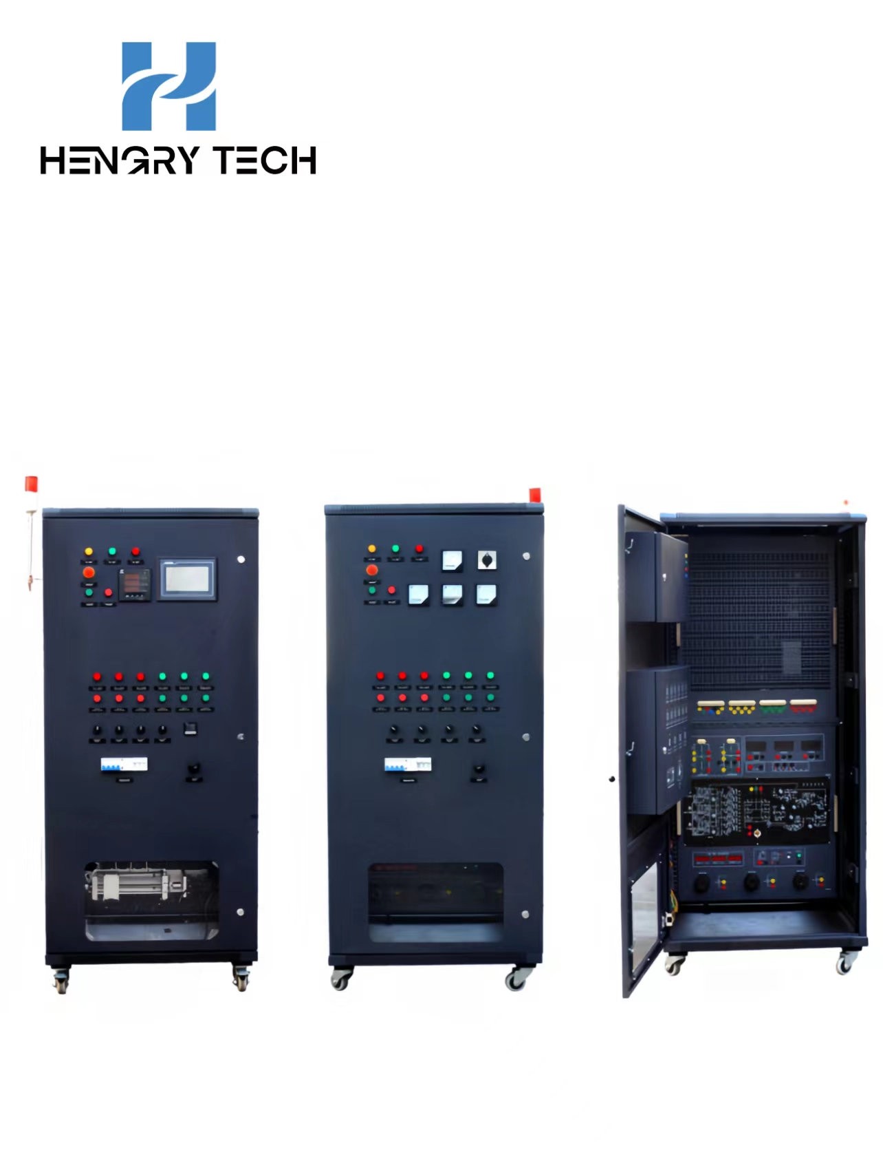

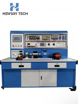
Technical parameters
1、Working power supply: three-phase five-wire AC 380 V±10% 50 Hz;
2, equipment size: L × W × H = 850mm × 800mm × 1700mm;
3, computer desk external dimensions: length × width × height = 600 mm × 530 mm × 1000 mm;
4, the desk frame material: cabinet steel structure;
5, the whole machine consumes apparent power: ≤ 1 KVA;
OVERVIEW
HRE-210 Electrical control technology assessment trainer is based on the higher vocational school of electromechanical equipment installation and maintenance, electromechanical technology application, electrical operation and control, electrical technology application and electronic appliances application and maintenance, and non-electrical majors, such as "electrician technology", "electrician basic skills", "the DC Motor Control", "Electrical Measurement and Instrumentation", "Electrical Machines and Electrical Control", "PLC Comprehensive Control", "Motor Control Circuits", "Power Tractor Control Circuits", "Power Electronics" and other related professional modules of vocational competence teaching and practical training, and takes into account the teaching requirements of secondary vocational schools.
Functions of practical training and assessment equipment
Examples of functions of practical training and assessment:
1. measurement of three-phase voltage by connecting the transfer switch to the voltmeter;
2. measurement of three-phase current;
3. The use of power integrated display meter;
4. control circuit connection for direct starting and stopping of three-phase asynchronous motors;
5. contactor interlocked three-phase AC asynchronous motor forward and reverse control circuit connection;
6. connection of the forward and reverse control circuit of the three-phase AC asynchronous motor with push-button interlock;
7. the connection of the positive and negative rotation control circuit of the three-phase AC asynchronous motor with push-button and contactor interlocking;
8. universal transfer switch to control forward and reverse rotation of three-phase asynchronous motors;
9. Connection of three-phase AC asynchronous motor Y-△ (manual switching) starting control circuit;
10. Connection of three-phase AC asynchronous motor Y-△ (time relay switching) starting control circuit;
11. Connection of stator winding series resistance starting control circuit;
12. Connection of three-phase AC asynchronous motor energy braking control circuit;
13. Connection of reverse braking control circuit for three-phase AC asynchronous motor;
14. Connection of sequence control circuits for multiple (3 or less) motors.
15. connection of control circuits for round-trip travelling of electric motors;
16. Connection of control circuits for ordinary lathes;
17. Connection of control circuit of electric hoist;
18. the connection of control circuits for three-phase AC asynchronous motors capable of both pointing and continuous rotation;
19. connection of two-ground control circuits;
20. the connection of the speed control circuit of a two-speed motor switched by a push-button;
21. the connection of the two-speed motor speed control circuit for time relay switching;
22. the connection of centrifugal switch cooperating reverse braking control circuit;
23. inverter panel function parameter setting and operation training;
24. Frequency converter to motor point control, start-stop control;
25. Multi-segment control of motor speed;
26. Industrial frequency, frequency conversion switching control;
27. Motor open-loop speed regulation based on analogue control;
28. Motor open-loop speed regulation based on panel operation;
29. inverter protection and alarm function training;
30. open-loop speed regulation of frequency converter based on PLC;
31. Use of analogue modules
32.PLC control of motor sequential starting;
33. PLC control of three-phase asynchronous motor Y-△ starting circuit;
34. Parameter setting of touch screen editing interface;
35. Screen configuration of touch screen;
36. Comprehensive practical training of touch screen, PLC and inverter;
37. Parameter setting of stepper driver;
38. PLC open-loop control of stepper motor;
39. The use of incremental encoder;
40. Practical training of encoder-based stepper motor;
41. AC servo motor control;
42. Parameter setting of AC servo drives;
43. PLC control of AC servo motors;
44. Practical training of encoder based servo motors;
45. Use of RTD or thermocouple;
46. Parameter setting of temperature controllers;
47. PLC temperature control based on RTD (thermocouple);
48. analogue based PLC control;
49. use of sensors;
50. PLC position control based on sensors;
51. DC it excitation motor speed, torque and power measurement and control;
52. Current regulation circuits;
53. open loop control of thyristor DC motor speed regulation;
54. Thyristor DC motor speed regulation closed loop control;
55.X62W milling machine electrical control circuit unit common fault checking and troubleshooting practical training (can be set up 16 fault points);
56.T68 boring machine electrical control circuit unit common fault checking and troubleshooting, (16 fault phenomena);
T68 boring machine electrical control circuit fault phenomena:
1. All motors are out of phase and the control circuit fails;
2. spindle motor and table feed motor, regardless of positive and negative rotation are missing phase, the control circuit is normal;
3. The spindle positive rotation is missing a phase;
4. One phase is missing in both positive and negative spindle rotation;
5. The spindle motor low-speed operation brake solenoid YB can not act;
6. The feed motor is missing a phase when it is moving forward rapidly;
7. The feed motor lacks a phase regardless of forward and reverse rotation;
8. The control transformer lacks one phase, and the control circuit and lighting circuit are without power;
9. Spindle motor positive rotation and start-up are invalid;
10. All control circuits are invalid;
11. The spindle motor reversal pointing and starting are invalid;
12. The high and low speed operation of spindle motor and the rapid movement of rapid traverse motor can not be started;
13. The low speed of spindle motor can not be started, high speed, no low-speed transition;
14. The high-speed operation of the spindle motor fails;
15. Rapid traverse motor, regardless of forward and reverse rotation are invalid;
16. Rapid traverse motor positive rotation can not start.
Milling machine electrical control circuit fault phenomenon:
1. spindle motor positive and negative rotation are missing a phase, feed motor, cooling pump is missing a phase, control transformer and lighting transformer are no power;
2. spindle motor regardless of positive and negative rotation are missing a phase;
3. The feed motor lacks one phase in reverse rotation;
4. Fast feed solenoid can not act;
5. Lighting and control transformer no power, lighting does not light, control circuit failure;
6. control transformer no power, control circuit failure;
7. Lighting lamp does not light up;
8. Control circuit failure;
9. Control circuit failure;
10. Spindle brake failure;
11. The spindle can not start;
12. The spindle cannot be started;
13. Table feed control failure;
14. table downward, rightward, forward feed control failure;
15. Table backward, upward and leftward feed control failure;
16. Two fast feed all failed.
Contact: Gustavo Zhang
Phone: +86 18966252578
Tel: +86-577-67318236
Email: Gustavo@hengrytech.com
Add: Yongjia county, wenzhou city, zhejiang province ou the five-star industrial zone north street