Email: Gustavo@hengrytech.com Tel: +86-577-67318236
![]()
![]()
![]()
![]()
![]()
Email: Gustavo@hengrytech.com Tel: +86-577-67318236
![]()
![]()
![]()
![]()
![]()

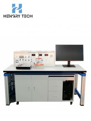
Equipment technical indicators
1. Working power supply: three-phase AC 380 V±10% 50 Hz
2. External dimension: 1600×750×1700mm
3. Machine power: ≤1.5KW
4. Ambient temperatures: -5 ℃ ~ +40 ℃; relative humidity: ≤ 90% (25 ℃)
Safety protection measures: the desktop of the laboratory bench is made of high density board with high insulation, high strength and high temperature resistance.
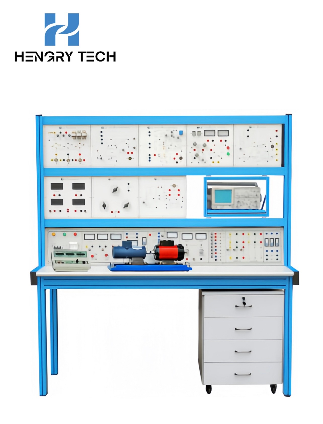
Equipment Overview
HR-DG03 Electrical & Electronic Technology and Automatic Control Trainer is based on the requirements of the current advanced manufacturing technology, reference to the typical industrial product lines, the use of modular structure, from the creation of an engineering environment, systematic training of students' ability to start after years of improvement in the design and the launch of new products. Product. It is applicable to the electrical engineering, automation, applied electronics, power supply and other types of professional "power electronics", "semiconductor converter technology", "motor and power drag control system", "automatic control principles and systems", "automatic control system", "DC speed control system", "AC speed control system", "motion control system" and other courses of the experimental training requirements. It is also applicable to the training and examination of senior electrician and senior electrician technician.
Functional features of the equipment
1. movable frame: the frame can be put on top of the hanging board module, can be expanded at will, to complete a variety of experiments with multiple doors, and another configuration of a movable cabinet, convenient for storing the required tools and experimental connecting wires.
2. 380V from three-phase power supply through the isolation transformer isolation, the device is powered by three-phase power supply, and is equipped with air switches with leakage protection, fuses to ensure the safety of use.
3. provide a number of groups of AC and DC power supply, and a variety of basic instruments, for students to carry out comprehensive experiments to provide a basic platform.
4. The device consists of unit modules, easy to replace, easy to maintain; the module itself is made of PCB baking varnish process, the front side of the schematic diagram and test points, the back side of the corresponding components welded to avoid the interference caused by the lead, greatly reducing the failure rate.
5. Embodying the concept of "engineering environment", imitating the actual production site: these systems are basically transplanted from related industrial products, which can well realize the cultivation of students' abilities (waveform analysis and system debugging ability) and the application of technical knowledge.
6. The configuration of each system is well-designed and colorful: the components, triggering (driving) circuits, main circuits, control modes, control objects and protection links adopted by each system are basically different, which summarize the current technical applications in the industry, are rich and varied in content, reflecting the requirements of "typicality, advancement, practicability and feasibility", and can arouse the students' ability (waveform analysis and system debugging ability). The content is rich and varied, reflecting the requirements of "typicality, advancement, practicability and feasibility", which can arouse students' interest and make them gain a lot.
7. Power electronic components and unit circuit performance experiments, in a small system environment: this is conducive to students' understanding of the components and the unit for where they are used, their performance on the impact of the entire system, is conducive to the consolidation of student knowledge and practical application.
Basic project experiments
1, trigger (drive) unit circuit research
(1) Single junction transistor trigger circuit
(2) Sawtooth wave phase-shift trigger circuit (disaggregated components)
(3) KC05 integrated sawtooth wave trigger circuit
(4) KC08 zero crossing trigger circuit
(5) EXB841 large-scale integrated (IGBT) driver circuit
(6) three-phase KC785 pulse train trigger circuit
2, power electronic circuits
(1) single-phase thyristor semi-controlled bridge rectifier circuit
(2) three-phase thyristor fully controlled bridge rectifier circuit (including three-phase half-wave, three-phase semi-controlled bridge)
(3) BJT single-phase parallel inverter circuit
(4) single-phase bidirectional thyristor AC power conditioning circuit
(5) DC (IGBT) chopper circuit and step-up and step-down circuits
(6) Single-phase (bidirectional thyristor) AC voltage regulation circuit
(7) Three-phase (anti-parallel thyristor) AC voltage regulation circuit
(8) SPWM-controlled single-phase AC/DC converter circuits
(9) PWM control (MOSFET) switching regulator circuits
3, automatic control system
(1) negative feedback voltage, current positive feedback, DC speed control system
(2) speed, current double closed-loop irreversible DC speed control system
Contact: Gustavo Zhang
Phone: +86 18966252578
Tel: +86-577-67318236
Email: Gustavo@hengrytech.com
Add: Yongjia county, wenzhou city, zhejiang province ou the five-star industrial zone north street