Email: Gustavo@hengrytech.com Tel: +86-577-67318236
![]()
![]()
![]()
![]()
![]()
Email: Gustavo@hengrytech.com Tel: +86-577-67318236
![]()
![]()
![]()
![]()
![]()
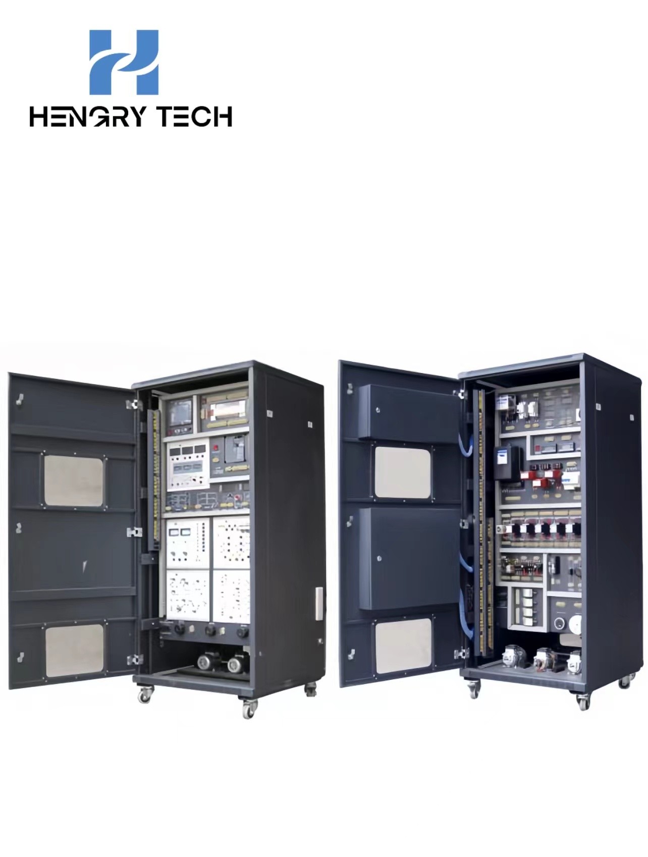

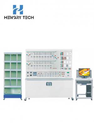
Technical parameters
1. Working power supply: three-phase five-wire power supply AC 380 V/220 V 50 Hz;
2. External dimensions: length (mm) × width (mm) × height (mm) = 800 × 850 × 1800;
3. Load capacity: ≤1kVA.
4. DC power supply: DC 0--10V output, 4--20mA current.
5. Safety protection:
1) Leakage protection action current: ≤30mA,
2) Leakage protection action response time: ≤ 0.1S;
3) With over-current, overload, leakage protection measures, in line with relevant national standards.
Equipment Overview
HRE-209 Modern electrician technology assessment practical trainer is suitable for higher vocational schools, secondary vocational schools of electromechanical equipment installation and maintenance, electromechanical technology application, electrical operation and control, electrical technology application and electrical application and maintenance of electronic and electrical appliances and other professional and non-electrical professional "electrician technology", "electrician basic skills", "electrician measurement and instrumentation", "motor and electrical control", "motor control circuits", "power drag control circuits" and other related professional modules Technology", "Basic Skills for Electricians", "Measurement and Instrumentation for Electricians", "Electrical Machines and Electrical Controls", "Motor Control Circuits", "Power Tractor Control Circuits" and other related professional modules of vocational ability teaching and practical training.
Functions of practical training and assessment equipment
1) Examples of practical training and assessment contents:
1)Practical training of day-off light;
2)Measurement of three-phase voltage by connecting transfer switch and voltmeter.
3)Measurement of power factor;
4)Real-time measurement of three-phase current;
5)real-time measurement of three-phase voltage;
6)Control circuit connection for direct starting and stopping of three-phase asynchronous motors;
7) connection of the control circuit for forward and reverse rotation of three-phase AC asynchronous motors with contactor interlocking;
8) connection of control circuits for forward and reverse rotation of three-phase AC asynchronous motors with push-button interlocking;
9) the connection of the forward and reverse rotation control circuit of the three-phase AC asynchronous motor with push-button and contactor interlocking;
10) universal transfer switch to control forward and reverse rotation of three-phase asynchronous motor;
11) connection of Y-△ (manual switching) starting control circuits for three-phase AC asynchronous motors;
12) connection of Y-△ (time relay switching) starting control circuit for three-phase AC asynchronous motor;
13) connection of stator winding series resistance starting control circuit;
14) Connection of three-phase AC asynchronous motor energy braking control circuit;
15) connection of the reverse braking control circuit for three-phase AC asynchronous motors;
16) connection of sequence control circuits for multiple (3 or less) motors
17)connection of round trip control circuits for electric motors;
18) direct start-stop control of DC motors;
19)Forward and reverse rotation control of DC motors;
20) Experiments on speed control of DC motors;
21)Connection of control circuit of ordinary lathe;
22)Connection of control circuit of electric hoist;
23)Connection of control circuits for three-phase AC asynchronous motors capable of both pointing and continuous rotation;
24)Connection of control circuits for two places;
25) the connection of a two-speed motor speed control circuit for push-button switching;
26) connection of a two-speed motor speed control circuit for time relay switching;
27) the connection of the centrifugal switch-cooperated reverse braking control circuit;
28)inverter panel function parameter setting and operation practical training;
29)frequency converter to motor pointing control, start-stop control;
30)motor speed multi-segment control;
31)industrial frequency, frequency conversion switching control;
32)motor open-loop speed regulation based on analogue control;
33)open-loop speed regulation of motor based on panel operation;
34)inverter protection and alarm function practical training;
35)PLC based open loop speed regulation of inverters;
36)Practical training in the use of general PLC instructions;
37)PLC control of motor sequential starting;
38) PLC control of traffic lights practical training;
39)PLC control of three-phase asynchronous motor Y-△ starting circuit;
40)Parameter setting of touch screen;
41) touch screen programming;
42) touch screen, PLC, inverter integrated practical training;
43)simple practical training of two-phase hybrid stepper motor;
44)Simple practical training of AC servo motor;
45)X62W milling machine electrical control circuit unit common faults in the inspection and elimination of practical training (can set up 16 fault points);
46) T68 boring machine electrical control circuit unit common fault checking and troubleshooting practical training (can be set up 16 fault points);
Milling machine electrical control circuit fault phenomenon:
1) the spindle motor positive and negative rotation are missing a phase, feed motor, cooling pump missing a phase, control transformer and lighting transformer are no power;
2) spindle motor regardless of positive and negative rotation are missing a phase;
3) The feed motor lacks one phase in reverse rotation;
4) Fast feed solenoid can not act;
5) Lighting and control transformer no power, lighting does not light, control circuit failure;
6)Control transformer is out of power, control circuit failure;
7)Lighting lamp does not light up;
8)control circuit failure;
9)control circuit failure;
10)Spindle brake failure;
11)The spindle cannot be started;
12)The spindle cannot be started;
13)Table feed control fails;
14)Failure of table downward, rightward and forward feed control;
15)Table backward, upward and leftward feed control failure;
16) two fast feed all failed.
T68 boring machine electrical control circuit failure phenomenon:
1) all motors phase loss, control circuit failure;
2) spindle motor and table feed motor, regardless of positive and negative rotation are out of phase, the control circuit is normal;
3) The spindle positive rotation is missing a phase;
4) Spindle positive and negative rotation are missing a phase;
5) spindle motor low-speed operation brake solenoid YB can not act;
6) The feed motor is missing a phase when it is moving forward rapidly;
7)The feed motor lacks a phase regardless of forward and reverse rotation;
8) The control transformer lacks a phase, and the control circuit and lighting circuit are without power;
9) The spindle motor positive rotation and start are invalid;
10) All control circuits are invalid;
11) the spindle motor reversal point and start are invalid;
12) The spindle motor's high and low speed operation and the rapid movement of the rapid traverse motor can not be started;
13) The low-speed spindle motor can not be started, high-speed, no low-speed transition;
14)The high speed operation of the spindle motor fails;
15) Rapid traverse motor, regardless of forward and reverse rotation are invalid;
16) Rapid traverse motor cannot be started in positive rotation.
Contact: Gustavo Zhang
Phone: +86 18966252578
Tel: +86-577-67318236
Email: Gustavo@hengrytech.com
Add: Yongjia county, wenzhou city, zhejiang province ou the five-star industrial zone north street